

I am finally reaching out as I am at my wits end and need experienced people to help me resolve my printing issue.
I have a Voxelabs Aquila (Ender 3 v2) formerly running marlin with small but manageable annoyances like overhang and manual bed leveling and thus began my journey after a year of using Aquila to start modding/upgrading the thing.
First thing i did was upgrade the fans and shroud, this improved prints slightly but was still not satisfied.
Moved to Klipper and added BLTouch and this is where all my problems started. After hours of following guides and troubleshooting of setting them both up, i still get very little bed adhesion and layers are not smooth together (gaps) with the same 3d slicing software i have been using before the switch (yes changed it to Klipper firmware in slicer)
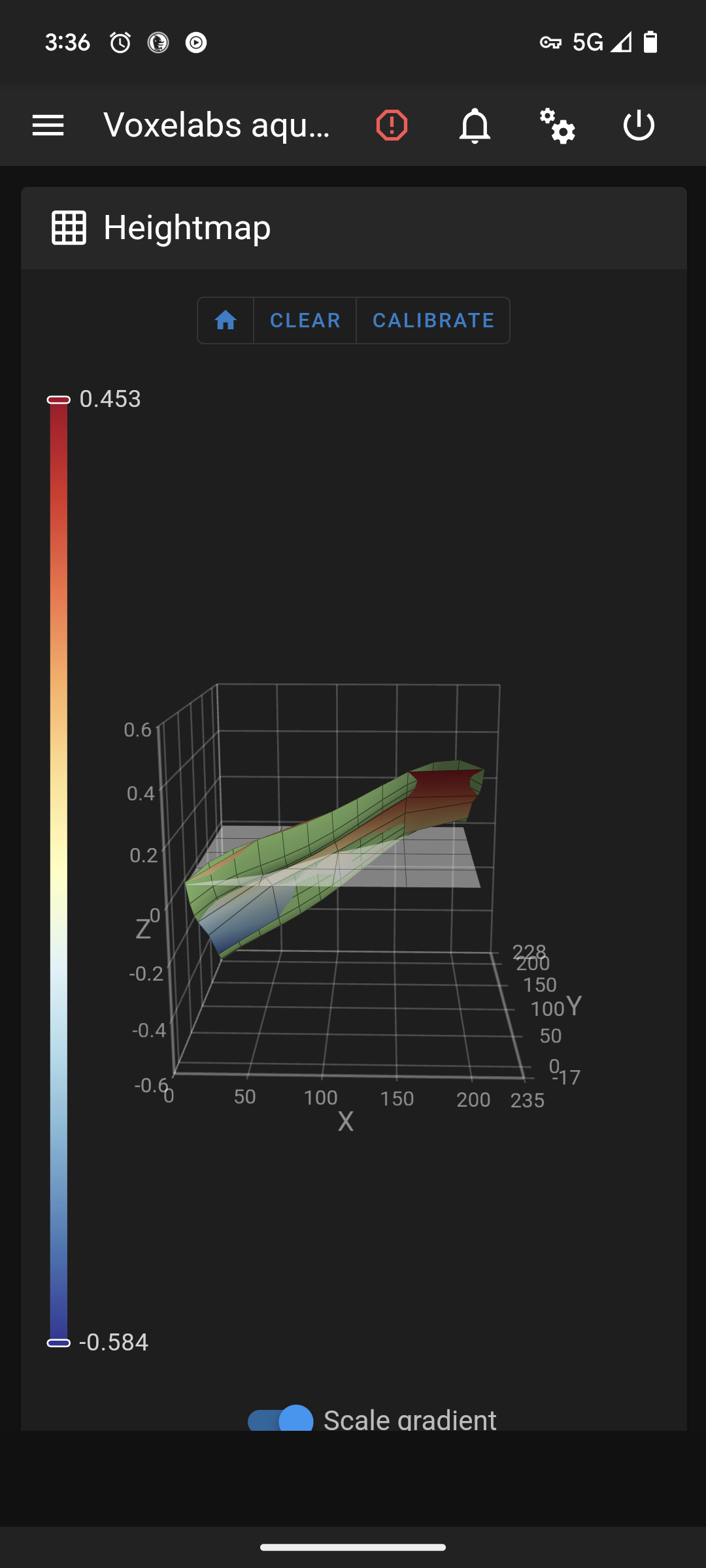
As you can see in the picture this is after a manual bed level. Where do i go from here?
Edit 2: fully cleaned nozzle, hotend, and bed without any other changes with same results.
Edit 1: forgot to add my printer.cfg
[include mainsail.cfg]

[stepper_x]
step_pin: PC2
dir_pin: PB9
enable_pin: !PC3
microsteps: 16
rotation_distance: 40
endstop_pin: ^PA5
position_endstop: 3
position_max: 235
homing_speed: 50

[stepper_y]
step_pin: PB8
dir_pin: PB7
enable_pin: !PC3
microsteps: 16
rotation_distance: 40
endstop_pin: ^PA6
position_endstop: -17
position_max: 228
position_min: -17
homing_speed: 50

[stepper_z]
step_pin: PB6
dir_pin: !PB5
enable_pin: !PC3
microsteps: 16
rotation_distance: 8
endstop_pin: probe:z_virtual_endstop
#position_endstop: 0.0
position_max: 250
position_min: -6

[extruder]
max_extrude_only_distance: 100.0
step_pin: PB4
dir_pin: PB3
enable_pin: !PC3
microsteps: 16
rotation_distance: 34.406
nozzle_diameter: 0.400
filament_diameter: 1.750
heater_pin: PA1
sensor_type: EPCOS 100K B57560G104F
sensor_pin: PC5
#control: pid
# tuned for stock hardware with 200 degree Celsius target
#pid_Kp: 21.527
#pid_Ki: 1.063
#pid_Kd: 108.982
min_temp: 0
max_temp: 250

[bltouch]
# Can't move this configuration to include because of z-offset adjustment
sensor_pin: ^PB1
control_pin: PB0
x_offset: -28
y_offset: -15
#z_offset = 0
samples: 2
speed: 2
#pin_move_time: 0.500
#probe_with_touch_mode: False
#pin_up_reports_not_triggered: True
#pin_up_touch_mode_reports_triggered: True
#stow_on_each_sample: False

[safe_z_home]
home_xy_position: 125,125 #this should be the center of your bed
speed: 50
z_hop: 10
z_hop_speed: 5

[bed_mesh]
speed: 80
horizontal_move_z: 5
mesh_min: 3, 33       #!!min and max co-ords are based on the probes location not the nozzle!!
mesh_max: 207, 213  #needs to be calibrated for your individual printer
probe_count: 5,5 #this is the number of probing points on X then Y axis
mesh_pps: 2,2
fade_start: 1
fade_end: 10
fade_target: 0

[bed_screws]
screw1: 25, 25
screw2: 195, 25
screw3: 195, 195
screw4: 25, 195

[heater_bed]
heater_pin: PA2
sensor_type: EPCOS 100K B57560G104F
sensor_pin: PC4
#control: pid
# tuned for stock hardware with 50 degree Celsius target
#pid_Kp: 54.027
#pid_Ki: 0.770
#pid_Kd: 948.182
min_temp: 0
max_temp: 130

[fan]
pin: PA0

[mcu]
serial: /dev/serial/by-id/usb-1a86_USB_Serial-if00-port0
restart_method: command

[printer]
kinematics: cartesian
max_velocity: 300
max_accel: 3000
max_z_velocity: 5
max_z_accel: 100

#*# <---------------------- SAVE_CONFIG ---------------------->
#*# DO NOT EDIT THIS BLOCK OR BELOW. The contents are auto-generated.
#*#
#*# [extruder]
#*# control = pid
#*# pid_kp = 31.251
#*# pid_ki = 2.510
#*# pid_kd = 97.268
#*#
#*# [heater_bed]
#*# control = pid
#*# pid_kp = 69.577
#*# pid_ki = 1.022
#*# pid_kd = 1184.541
#*#
#*# [bltouch]
#*# z_offset = 3.609
You must log in or register to comment.
Before going any further to adjust your Z offset and other factors to tune for better bed adhesion, you should probably adjust your bed to actually be level as well as ensure (seeing that you only have one z lead screw?) that the X axis frame isn’t sagging on the side not containing your Z lead screw. Once you’ve got those factors sorted out, you should check your probe repeatability and then set your Z offset accordingly.
Bed adhesion even with proper, clean first layers can be a pain depending on the bed surface, material being printed, how clean the bed is of oils and other contaminants, how hot the material is being extruded, and how hot the bed is among other factors. While using a bed mesh will greatly help to account for off-zero unevenness in your bed surface, you really shouldn’t use it to compensate for uneven bed leveling (especially when it looks like you are nearing more than 0.5 mm in unevenness).
To diagnose other print issues, it will be helpful to see a picture showcasing the problems described in a failed print.
As a side note, it is somewhat difficult to read your Klipper config file without using view source as it is being markdown formatted. You can negate it by using three graves on the lines above and below it so that it is wrapped in a ‘code block’ and isn’t formatted.
```
Some code
  eeeee
  fffff
```Turns into
Some code eeeee fffffThanks, i have updated my post with proper markdown sorry about that. I will level it again and increase the z offset to flatten the print for better adhesion (while i have done this before wouldnt hurt to do it again)
Your bed is probably warped. It’ll be level at the points you measured, but way off elsewhere. Get a straightedge or a ruler and check it. Shim the low spots with aluminum foil folded over on itself. Even glass beds have some bend in them and will not be level when you clip them to the edges.
Don’t use the paper method, it’s not accurate. Buy a feeler gauge off Amazon for $10.
Increase the number of spots to measure for your bed mesh.
Reduce the gap between the nozzle and the bed for PLA. I usually use anywhere between -0.4mm all the way up to -1.5mm z offset. Increase the gap for PETG
Thanks, i think going to buy the feeler gauge for better precision.
One thing that was driving me crazy was that even when I manually leveled, I wasn’t getting uniform leveling as I expected. Turns out that klipper doesn’t automatically load the measured grid automatically. So basically after I ran the bed leveling, it requires a restart to save, but doesn’t load on start. Once I realized that, I made a habit of just loading the mesh manually each time it restarted. Started getting expected leveling results after that.
I took too long to learn this too. Even with it leveled via bltouch, i still have adhesive issues.
I suggest looking into macros which will allow you to set your mesh profile in gcode which will resolve any manually selecting of mesh. This is my next step after i fix this major issue I’m having.
Are you calling the mesh something other than “default?” Mine will load the previous mesh automatically. I believe you have to change the config to use your preferred name as the default mesh instead of using “default” in the config.
I had the same issue too. Idk what its related to but learned this hard way too. Im moving to macros in gcode after i get the main issue fixed and doing so will let me select the mesh name.
As far as adhesion goes, what print surface are you using? I personally have found that a glass bed with aqua net hairspray works better than any other combo that I’ve tried. I almost never have any issues with adhesion using PLA or PETG.
Glass bed that came with printer. Only printing PLA.
Are you using anything on the bed?
I am not, never have. Always clean it with Isopropyl 70% or greater after about 5 prints or if it sits unused for a lengthy amount of time
I seldom had any good adhesion on clean glass. But cheap hairspray works wonders for me. Gives it something to stick to, but also functions as a release agent. Especially helpful if you ever use PETG, because it’s been known to actually bond to the glass.
I’ve always used the name default. I’ll look into changing it in the config.
Not sure what the issue is here then as this is how I’m running mine as well. I didn’t have to make any changes to the config.
What version of klipper are you using? I know it used to auto load the default profile, but they changed it about a year ago to require you to manually set it, either with a macro or in gcode itself.
Not sure on the version. It should be updated to the latest or nearly the latest version.
New Lemmy Post: Klipper from marlin, tons of issues (https://lemmy.world/post/12409369)
Tagging: #3dprinting(Replying in the OP of this thread (NOT THIS BOT!) will appear as a comment in the lemmy discussion.)
I am a FOSS bot. Check my README: https://github.com/db0/lemmy-tagginator/blob/main/README.md
Seems like your bed is sloped. Have you used the corner leveling tool as described here? https://www.klipper3d.org/Manual_Level.html#adjusting-bed-leveling-screws
Yes, many times. Going to try what others have suggested and will update. Thanks for your suggestion :)
I’ve got a Frankender myself and have been using Klipper for a few years.
I’ve been where you are and I understand the frustration.
I’m assuming your range is high enough to warrant it. The scale of the height map can be deceiving. For example my Frankender is relatively well tuned now and its range (with the not so flat stock bed) when the bed is heated is about 0.09. That’s quite a bit less than a layer height and so it’s not an issue. Could be you’re in the same boat.
So let’s take a step back and look at it fresh.
- Physical
- Kinematics
- Adjustments and corrections.
1a. Let’s make sure your gantry is square.
I’ll list them here but you can find slot of this in this video
-
loosen and then gently tighten the screws. Really just “snug” is good. Over tightening cannot only strip the aluminum threads but also “twist” the extrusion subtly (this one took me a week to find)
-
use a square (even a carpenters square if it’s all you have) and make sure that the Z extrusions are square with the X direction extrusions they mount to. If they’re not loosen the appropriate screws and, if needed, use small flat folds of aluminum foil to get them right)
-
Make sure your Z extrusions are parallel and not rotated compared to each other. Use something rigid and square (such as the X gantry extrusion if it’s undone) to align their faces.
And, while you’re at it, if the X extrusion is off anyway go ahead and find a flat reference surface (granite countertop, glass top range… carefully on this one) and make sure it’s not twisted (see more here https://youtu.be/qju5RECjVUM)
-
Make sure your actual Z gantry isn’t diverging/leaning inwards as it gains height (if you use a Squarish rule and put it on your X gantry as you slowly move it up and check that the distance is relatively the same. Won’t be perfect hit shouldn’t be obviously wrong. Again loosen the screws and then tighten them with a little more “snug” on the inner or outer set of screws to align them. You’ll probably have to loosen the top mount screws to give them room to move and then gently snug them.
-
Make sure the X gantry is parallel with the top frame. Bring it up and then make sure it’s consistently the same distance on the left and right. If not then adjust the screws on the mounting brackets that ride on the Z extrusions and get it close. Then, again, gently tighten them just past snug. Too much here and you can introduce the twisting I mentioned above… that one cost me a week once and is the reason I know about skew_compensation. Of course once loosened the issue was fixed and thankfully wasn’t something with the frame.
-
Make sure the Y gantry is also straight (to lessen XY skew) as much as possible by checking that the distance between it and the two size extrusions the Z’s mount to are relatively parallel. Loosen the 4 screws beneath the printer, straighten it and tighten… again just past snug.
1b. That covers the frame. Now for the physical motion.
- Adjust the wheel tension. If the wheel adjustment nuts are too tight you’ll get binding, flat parts, etc causing issues.
Can see an overview of this here
You’ll loosen them on the Y gantry first. Then tighten them so that, while you hold the bed with one hand, you can barely turn them with your other. If they turn easily tighten. If you can’t turn them without the bed moving… then loosen. They should barely turn with some resistance. When your done the bed should move freely but not “rock” or “pivot”
-
Now do the same for the X gantry. And you’re looking for the same results and likewise your X gantry should move freely but not “rock”.
-
Now do your Z wheels. Same as above.
-
Now for the belts. Too tight and they’ll wear out or break and strain your steppers. Too loose and you won’t get consistent movement.
There’s apps that you can use to pluck them and get them just right but I find the following works pretty well.
First the Y. Move the bed all the way back to the end stop and then “pluck” the belt on top. You want it to feel like it’s firm. Not a high pitch tone or a lot of resistant. More like your dangling an apple at the other end and you can feel the resistance. If it’s really loose or a low “thud” then tighten them.
Now do the X, move the X carriage all the way to the left and on the other side, on the bottom, do the same feeling for the same result.
1c. The bed tramming. Tighten all the screws all the way so that the bed is pulled low. Then rotate them back 2 full turns (e.g. looking from the top of the bed you’re going to turn them all 2 hours counter clock wise)
This will be done cold, you don’t need to hear the bed or nozzle. The BLTouch will handle the difference with expansion and you’ll have to adjust Z offset later. Right now what we want is your X gantry and carriage to be as close to parallel with your bed as possible. The X carriage isn’t going to be perfectly parallel with the ground, etc. but as long as the bed “matches” any tilt then it doesn’t matter. That’s what we’re tramming it for.
Now home your printer so that the motors are all engaged and using the UI move the toolhead just over the back left screw (where the bed wire retention assembly is). This is the screw you have less room to work with so I find it easier to make it my reference point.
Now using a piece of paper, a feeler gauge, anything consistent baby step the nozzle down until you just barely feel resistance. Then move it consistently up something like 5mm. Then move it over the opposite screw (the front right one). Then move the head down by 1mm 5 times. Basically we just want to be careful not to crash the head. If it’s obviously more than 5mm above then you can just move by 5.
So to recap we’ve positioned it at the reference screw touching the bed. This screw we’re not turning. Just bringing the nozzle to it. Then move the nozzle Z up 5, moved it over to a new screw, and then Z down by 5.
Now adjust the screw under front right of the bed bringing it up to the nozzle while testing with the paper/feeler and just when you feel like there’s some grab to it stop. If there’s too much then just tighten the screw until it’s right.
Now move up Z by 5mm, then move to the upper right screw and, just as before, bring it down by 5mm and adjust the screw until it touches the nozzle.
And do the same for the lower left screw.
Now home everything again… as we adjusted the screws the bed was pivoting ever so slightly… so we’ll do it again to fine tune the points.
Move over to the upper left, bring the nozzle down until you get the right resistance on the paper/feeler. Move up by 5, move to the front right screw, down by 5 and tweak the screws to match. Then do the same for the back right and front left screws. You should just about be trammed and you’ll find, as your doing this, that you don’t have to really adjust the screws much as it should already be about right as your “dialing it in”
So now you have a pretty good foundation for the next steps. Your physical printer is relatively square, things aren’t so tight that they’re twisting everything by a degree, but are tight enough to stay relatively where they should, The X Gantry is relatively parallel to its frame, and bed is relatively in line with the X gantry. Your belts are tight enough to reliably move the printer components without causing any issues. And your wheels are holding onto the extrusions so that your bed and X carriage aren’t twisting throwing off distances and skewing probes. But aren’t so tight that they deformed causing bumps and shifts as they move
Continued next reply
- Let’s make sure everything is reliable with the motion system.
Let’s go over the Klipper configuration checks.
https://www.klipper3d.org/Config_checks.html
I’ll assume you’ve already done the emergency stop M112 and thermal ones. If not definitely do them. Always good to be sure that Klipper can safely read temps, and reliably shut things down when it can’t.
Wait for things to cool down if anything’s been heated (such as the bed) and then
- Use M84 in the console.
Can you move the bed freely (but slowly) back and forth?
Can you rotate the Z Lead screw coupler and move the X gantry up and down!
Can you move the X carriage left and right?
- Check the end stops
Move the bed back to its switch. Then use QUERY_ENDSTOPS in the console and check what if reports for Y. Triggered, for example.
Now move it away from the switch. And do QUERY_ENDSTOPS again. Is the switch showing the right state now? Not triggered?
Do the same for X and, if you’re still using the Z limit switch then Z. Let’s make sure the endstops are triggering correctly. These are the means that Klipper has to get a sense of the physical world. After homing everything else is just keeping track of how it’s moved relative to what it knows is the home position (like a submarine navigator using charts and known direction and movement to plot a course)
- Check the steppers.
Home the printer and then move the nozzle so it’s over the center of the bed and move it up to about z100
Then run the following in the console. STEPPER_BUZZ STEPPER=stepper_y
The bed should move 1 mm towards you, then 1 mm towards the back.
Now run
STEPPER_BUZZ STEPPER=stepper_xThe X carriage should move 1mm to the right and then 1mm to the left.
And finally
STEPPER_BUZZ STEPPER=stepper_zThe X gantry should raise 1mm, then lower 1mm
If not then check the configs for changing the pins on the particular stepper. I’d be surprised if this was an issue as I can’t imagine it even homing correctly but we’re doing sanity checks. Assuming nothing so we can rule out things that will affect down stream problem solving.
- Validate the probe is reliable
Home the printer and then run the following
PROBE_ACCURACYThis should cause the probe to be deployed and tested repeatedly. What we’re looking for is the general same value as noted here
https://www.klipper3d.org/Probe_Calibrate.html
There will be some variation but if the results aren’t reliable then it can’t reliably be used for a mesh or homing, etc. of course sometimes it’s a matter of adjusting the speed. Sometimes it’s physical (for example a very loose X carriage which is why we made sure the V roller wheels are right)
Note the Klipper docs on what you’re looking for. It explains how to find the acceptable range based on your actual Z stepper micro steps). Can’t accurately measure something with a tool that gives results larger than the thing you want. E.g. baseball height with a yard stick.
Of course sometimes it’s just a matter of finding the right speed or fixing the carriage (which we covered). Or verifying the connection to the board is good (powered off, obviously) And if that doesn’t work then it may warrant getting a replacement but since it’s worked for you in Marlin it shouldn’t be an issue.
- Verify the extruder.
Disconnect the filament Bowden before it goes into the extruder. And let’s also make sure that any tensioner for the filament is tightened. Not looking for it to be super tight, again just snug enough that the filament will be engaged by the extruder gear and pushed.
Home the printer, then move the Z up to about 150 or so. And turn the hot end on to the proper temp for your filament. Go to the highest temp recommended for the filament if you can since we want to make sure we have the right rotation for the given extrusion amount and so we want to extrude hot and extrude very slowly so we aren’t “fighting” to push the plastic.
Now take a ruler and place one end against where the Bowden goes into the extruder. Then, keeping the filament in line as straight as possible with the ruler, find a spot that marks 150mm and use a marker or piece of tape.
Once the hot end is up to temp issue the following
G91
G1 E100 F60
What this does is set the movement to relative (G91) and the move G1 the E(extruder)100mm at a F(federate) of 60.
So move the extruder 100mm very slowly.
Wait for it to finish and then use your ruler to measure the distance between your mark or tape and the Bowden connection. We asked it to push 100mm, now we’re seeing how much is left of our 150mm. If it’s spot on it’ll be 50. But if it’s over or under then we can use that to adjust the rotation distance (how much to rotate a stepper to move a distance) for the extruder. E.g. this is the same as figuring out the Esteps in Marlin.
So we do a little math (or use excel or any number of online calculators) to calculate our new rotation distance.
Let’s hypothetically say your current rotation distance is 40
And we had 150mm filament and extruded 100. But we end up with 55mm left over (e.g. we under extruded)
Here’s the formula used in Klipper reference rotation_distance = rotation_distance = previous_rotation_distance * actual_extrude_distance / requested_extrude_distance
And we, hypothetically, had 51 mm left between our mark and the Bowden So that’s actual_extrude_distance =150-51 Or actual_extrude_distance =99
rotation_distance = 40 * (99 / 100)Or rotation_distance = 39.6
And so you’d set rotation_distance under your extruder to 39.6. Then save and restart Klipper so it uses the new value.
Then repeat the test. If you don’t end up with 50mm left over your calculate the new rotation_distance again being sure to use the value that was used (in the config) as of the time you ran it. E.g. in our hypothetical the second time would be with 39.6 instead of 40
Once it’s right connect your Bowden back
- Clean the build plate
After we’ve got all the bases covered let’s take the build plate off and give it a good wash in warm soapy water.
Give it a really good scrub and then dry it. Ideally using something like a shop towel to reduce any towel or napkin fibers getting on the plate. So many times this was the one thing causing me issues with first layer adhesion. It just needed a good wash.
Continued next comment (after I get some sleep. Check back in 10 hours or so) where we’ll do our Z offset with the actual filament until it flows right with our fancy overpowered glue gun like plastic extruder
Edit: Added build plate cleaning
- Adjustments and corrections.
- Make sure your probe offset is correct
I’m assuming you’ve done the BLTouch config checks here
https://www.klipper3d.org/BLTouch.html
Take a piece of painters tape and place it in the middle of the bed and using a fine tip pen out a small dot on it.
Now home your printer and then do the following
In the console enter the following
PROBENow move the tool head until you have the deployed probe over the dot on the tape. Then slowly baby step it down while adjusting the X and Y to put the probe directly over the dot.
Once you’re sure it’s directly overhead baby step down until the probe triggers and then enter the following in the console.
GET_POSITIONAnd note the toolhead X and Y
Recv: // toolhead: X:46.500000 Y:27.000000 Z:15.000000 E:0.000000Note the X and Y values.
Now move the toolhead so that the nozzle is over the dot and then bring it down slowly making sure it’s over the spot. When you’re sure it is do another GET_POSITION in the console.
Recv: // toolhead: X:41.500000 Y:29.000000 Z:15.000000 E:0.000000Now you can calculate the new X and Y offset.
Your probe X offset will be nozzle_x_position - probe_x_position
Or in our hypothetical example above
41.5 - 46.5Or x_offset: -5
And the probe Y offset will be
nozzle_y_position - probe_y_positionOr in our hypothetical example above
29 - 27Or y_offset: 2
Remove the tape and then restart Klipper and we should now have a reliable X and Y position. So when you home it Klipper should move the probe over the center of the bed and then move the nozzle over that same spot when asked to move to the same location.
- Z offset
You don’t have to heat the bed for this since we’re only calculating the distance between when the probe activates and the tip of the nozzle. Well be doing the Z offset as documented here
https://www.klipper3d.org/Probe_Calibrate.html
You can test this with the nozzle heated (that’s more accurate) but you don’t need to. That’s because we’re going to get close and then use a print to get the final detail.
So home your printer and then issue the following
PROBE_CALIBRATEThen we’ll use the same method as we did for the screws with paper or a feeler gauge.
Follow the prompts and once you have the slightest grab then you have the right spot.
Since we’re using a piece of paper we aren’t actually at 0 and you can adjust it down 0.1 (or whatever the thickness of your feeler gauge is)
Then you’ll enter
ACCEPT
SAVE_CONFIG
Now restart Klipper.
- Bed Mesh
Let’s warm the bed to your printing temps. Since we know the bed is trammed we don’t have to worry about adjusting the screws with it hot
In the console enter the following
G28
BED_MESH_CALIBRATE
When it’s done look at the bed mesh in the UI. What’s the range? If it’s less than your layer height you should be good. Focus more on the range and less on the visual since the scale can be confusing. It’s incredibly useful for seeing if there’s warping, or the bed is way out of tram but we’ve already physically confirmed that we have the kinematics fixed
Now save the config which will save this mesh SAVE_CONFIG
- Make sure your start print macro calls it
Here’s what mine looks like with a few things removed to avoid confusion
[gcode_macro START_PRINT]
variable_material_printed: ""
variable_material_retract: 1.2
gcode:
  {% set BED_TEMP = params.BED_TEMP|default(60)|float %}
  {% set EXTRUDER_TEMP = params.EXTRUDER_TEMP|default(180)|float %}
  {% set DO_ABL = params.DO_ABL |default(1)|int %}
  {% set MATERIAL = params.MATERIAL|default('PLA')|string %}

  ;Reset state
  G90 ; Absolute Positioning

  CLEAR_PAUSE

  M117 Starting {MATERIAL} Print with Bed Temp of {BED_TEMP} and Extruder Temp of {EXTRUDER_TEMP}, ABL set to {DO_ABL}
  PLAY_START

  # Save material used
  SET_GCODE_VARIABLE MACRO=START_PRINT VARIABLE=material_printed VALUE="'{MATERIAL}'"

  SFS_ENABLE ; Turn on filament runout

  G90 ; use absolute coordinates
  SET_PART_FAN PERCENT=20 ; Fan on approx. 20% to protect cooling ducts

  ;Start heating bed
  M117 Start > Heating Bed
  SET_HEATER_TEMPERATURE HEATER=heater_bed TARGET={ BED_TEMP } ; set bed temp

  G28 ; home all

  ;Move up to keep toolhead away from heating bed
  G1 Z75 F3000
  TEMPERATURE_WAIT sensor=heater_bed minimum={BED_TEMP} ; wait for bed temp

  {% if DO_ABL == 1 %}
    ;Pre-heat the extruder while we build the mesh so it'll be ready
    SET_HEATER_TEMPERATURE HEATER=extruder TARGET={ EXTRUDER_TEMP-50 } ; set first layer extruder temp

    M117 ABL
    BED_MESH_CALIBRATE PROFILE=default; calibrate bed mesh leveling

  {% else %}
    ; Load the existing mesh
    M117 Loading Default ABL
    BED_MESH_PROFILE LOAD=default ; Use default mesh
  {% endif %}

  ;Turn part fan off unless otherwise requested
  SET_PART_FAN PERCENT=0

  ;Home z after bed is heated
  G28 Z

  ;Park the head at the right location
  ;;Smart_Park

  ;Prepare
  M117 $MR$:Preparing to Print

  ;Heat extruder to final temp

  SET_HEATER_TEMPERATURE HEATER=extruder TARGET={ EXTRUDER_TEMP } ; set first layer extruder temp

  ;Turn on Nevermore filter
  SET_FAN_SPEED FAN=Nevermore SPEED=.8

  ;Wait for everything to be ready
  TEMPERATURE_WAIT sensor=heater_bed minimum={BED_TEMP} ; wait for bed temp
  TEMPERATURE_WAIT sensor=extruder minimum={EXTRUDER_TEMP} ; wait for extruder temp

  M117 Start > Priming

  ;Draw Primer Line
  NOZZLE_PRIME_LINE

  G92 E0.0
Don’t copy this but it can be useful to see the order of how I have my mesh and heating, etc.
- Final adjustment of your Z offset with a print
In your slicer of choice we just need a patch that’s the same height as your layer height (such as .2) you can find one online, create one or even download this one from Andrew Ellis’ GitHub.
https://github.com/AndrewEllis93/Print-Tuning-Guide/tree/main/test_prints
As it’s printing watch it and use the baby step ui to move it .01 up (if it’s over extruding and there’s ridges) or down (if it’s obviously too far and there’s gaps)
Then, when it’s done you hit the save icon or enter this in the console
Z_OFFSET_APPLY_PROBEThen save_config to save the value.
Run the print again and verify that you have a smooth solid print that matches what you see here in the phenomenal Ellis print tuning guide
https://ellis3dp.com/Print-Tuning-Guide/articles/first_layer_squish.html
Hopefully that helps and if it doesn’t there’s more that can be accounted for and adjusted but it’s always good to make sure we have the fundamentals.
The skewed and twisted X gantry took me a week of frustrating prints and tweaks before I stopped, redid the frame, etc and identified the issue.
This needs to be posted somewhere more permanent, serious contribution right there
If I get a chance I can try and clean it up a bit and make it its own post perhaps
Please do this is great! Fills in gaps I found with other guides I’ve run into.
You’re a goddamn legend. I’m new to 3D printing and have had issues of my own trying to learn how to calibrate Klipper, and your comments are more helpful than most of the other forum threads and guides that I’ve found. Thank you!
Happy to help. If you have any questions I’ll do my best to answer them.
Holy shit, you’re an absolute legend for going this far to help someone
Edit: OP is an asshat for not acknowledging youI just felt the frustration… and having been there myself I thought I could offer a moment to just step back and establish the basics.
Hey, you’re an absolute Chad for putting this much effort into helping someone, whether they acknowledge or not. Thank you!
It can be frustrating… sometimes we just need to make sure we have a good foundation for everything else.
Thanks! Followed this closely, I then decided to flip the glass bed to the smooth bottom side, for giggles, manual bed leveled then bltouch leveled, then decided to print to see if anything changed and it surprisingly printed and stuck very well the cleaned GLASS surface without anything else (i still dont honestly known how it sticks this well to glass). Im still getting some stringing and blobbing still so will continue following your amazing instructions(probably the broken cooling fan related and maybe a estep issue). Just wanted to give you an update that i am indeed following your instructions. So thanks again. Will update as i go along.
That’s great to hear. A lot of it is just stuff I encountered via videos (such as Nero 3D the Canuck Creator on Axis Twist) and a lot of Andrew Ellis guide which is invaluable.

